What is PoE? How does it work?
This article will introduce POE from 4 aspects: what is POE; why PoE is needed; how POE works; and non-standard implementation of POE.
What is POE?
POE, Power over Ethernet, refers to the transmission of power over Ethernet. It is a technology that allows power to be supplied to remote devices through Ethernet network cables while providing data transmission capabilities. Traditionally, devices required separate power lines, but with POE technology, power and data transmission can occur simultaneously through the network cable, greatly simplifying the complexity of power wiring and device deployment.
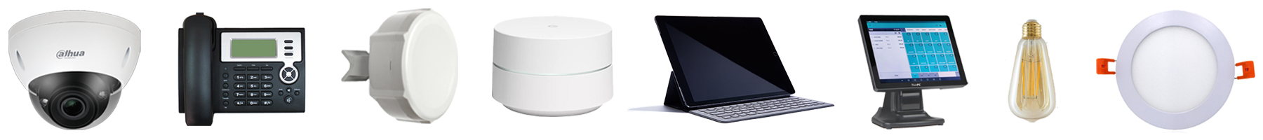
POE technology is typically used in devices that need to receive power from central network equipment, such as switches. Examples include IP cameras, VoIP phones, network cameras, LED lighting fixtures, and other network devices.
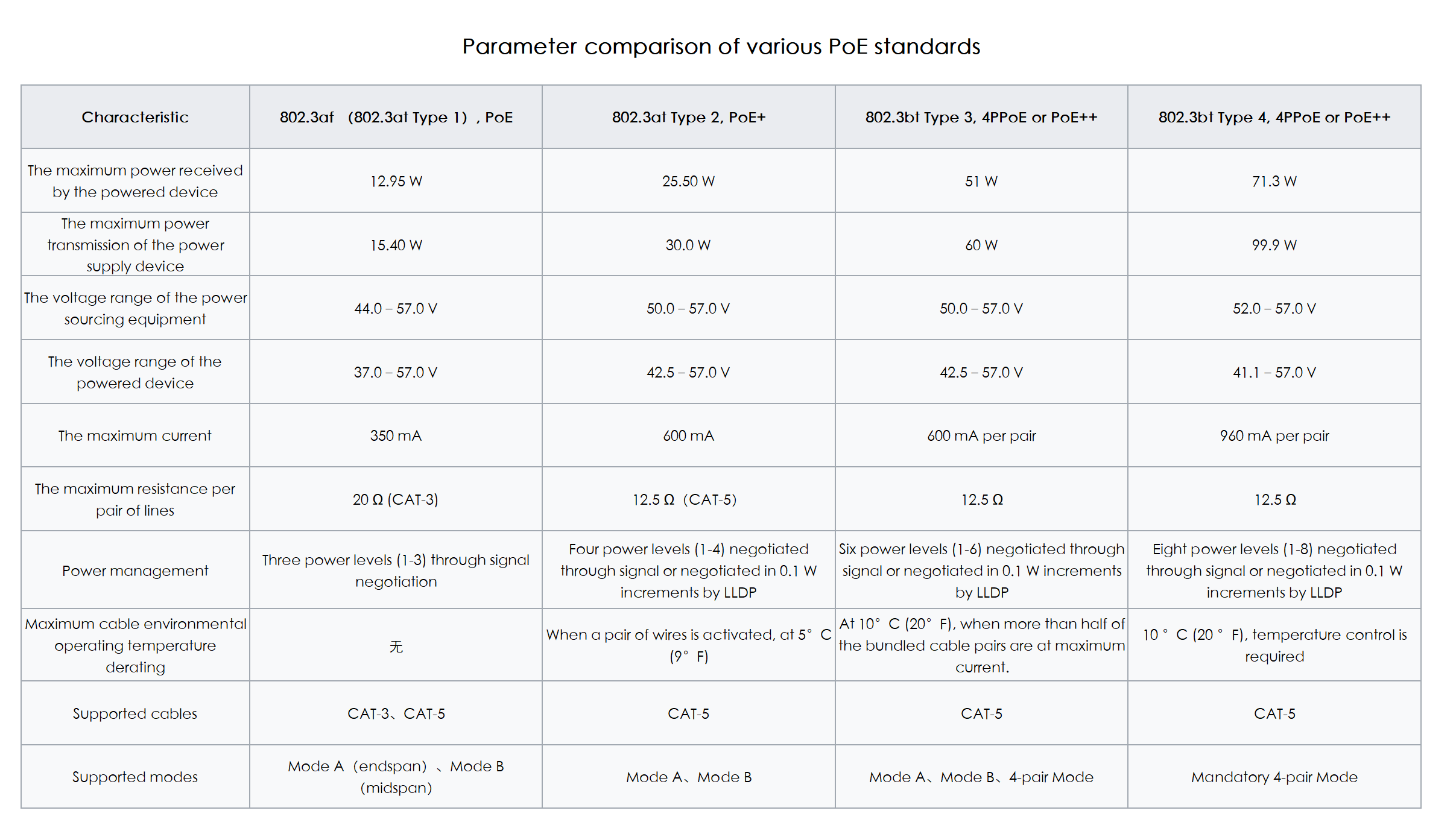
To standardize and promote the development of Power over Ethernet (PoE) technology, addressing compatibility issues between different manufacturers' power supply and powered devices, the IEEE Standards Committee has successively released three PoE standards: IEEE 802.3af, IEEE 802.3at, and IEEE 802.3bt.
The initial PoE standard was IEEE 802.3af, capable of providing a maximum of 15.4W of direct current power per interface. However, due to cable transmission losses, the actual powered devices could only receive up to 12.95W of power. The subsequent upgraded standard was IEEE 802.3at (also known as PoE+), providing a maximum power of 25.5W for Type 2 devices.
The standard released in 2018, IEEE 802.3bt (also known as PoE++ or 4PPoE), expanded the capabilities of 802.3at, offering two different power types: a maximum of 51W for Type 3 devices and a maximum of 71.3W for Type 4 devices. Each pair of twisted-pair cables can provide a maximum current of 600mA (Type 3) or 960mA (Type 4). Additionally, this standard supports power supply for 2.5GBASE-T, 5GBASE-T, and 10GBASE-T, providing a broader range of applications for high-performance wireless access points and surveillance cameras.
Why is POE needed?
With the widespread use of IP phones, network video surveillance, and wireless Ethernet devices, there is an urgent need to address power supply issues during the deployment of these devices. In many cases, these devices require direct current (DC) power and are often installed at elevated locations, such as ceilings or outdoors, where finding suitable power outlets nearby can be challenging. Even if outlets are available, it might be difficult to place the required AC/DC converters for the terminal devices.
In large local area networks, administrators need to manage multiple terminal devices simultaneously. However, traditional power supply methods, constrained by the location of power outlets, create significant inconvenience for power management. The advent of POE technology effectively addresses these issues by providing both data transmission and power support through a single Ethernet cable, simplifying the wiring and power supply process for devices.
POE technology is a wired Ethernet power supply technology that uses Ethernet cables to simultaneously transmit data and direct current, solving the centralized power supply challenges for terminal devices such as IP phones, wireless access points, portable device chargers, card readers, cameras, and data collection equipment. This technology is characterized by its strong reliability, simple connectivity, and standardized uniformity. Terminal devices do not require external power supplies, reducing dependence on power lines and outlets while cutting construction and maintenance costs. This flexible, economical, and straightforward power supply method offers an ideal solution for various devices in modern network applications.
Advantages of POE:
Simplified Wiring: POE provides data transmission and power supply through a single Ethernet cable, reducing the complexity of device wiring, making installations more flexible, and lowering the difficulty of maintenance and management.
Cost Reduction: POE technology eliminates the need for additional power lines and outlets, reducing construction and maintenance costs. Device installation and migration are more economically efficient.
Increased Flexibility: Devices are no longer restricted by the location of power outlets and can be installed more freely within the network range. This is particularly useful for devices that need frequent movement or in areas where accessing power outlets is challenging.
Ease of Maintenance: POE allows centralized power supply and management of devices in the network, simplifying device monitoring and maintenance. Administrators can achieve remote control of devices through centralized POE power supply equipment.
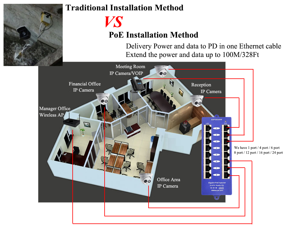
Support for Remote Devices: POE can provide power supply within a maximum distance of 100 meters, making it more convenient to deploy devices in remote or hard-to-reach areas.
Reliability: POE standards ensure the safe and reliable transmission of power and data. Through negotiation and control, they ensure matching and stability between power supply devices and powered devices.
Compatibility: POE adopts international standards and uses a standardized RJ45 interface, ensuring strong compatibility with devices from various manufacturers and simplifying device integration.
How does PoE work?
The working principle of PoE involves transmitting power over Ethernet cables to provide power to devices that require it. Power Sourcing Equipment (PSE) detects and negotiates the available power level, transfers power onto the Ethernet cable, and Powered Devices (PD) receive and utilize this power.
There are two main types of devices involved in the working of PoE: Power Sourcing Equipment (PSE) and Powered Devices (PD).
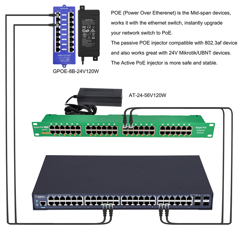
Power Sourcing Equipment (PSE): This is the device providing power, responsible for transmitting power onto the Ethernet cable. PSE can be a network switch, router, or a dedicated PoE injector. According to IEEE standards, PSE can detect and provide the appropriate power to PD. PSEs can be categorized as Endspan (network switches providing PoE directly) and Midspan (PoE injectors acting as an intermediary between non-PoE switches and PoE devices).
Powered Devices (PD): These are devices receiving power over the Ethernet cable. PDs can include various network devices such as IP cameras, wireless access points, and network phones. They are designed to be PoE compatible and capable of receiving power from PSE.
Powering Modes of PoE:
PoE has two main powering modes: Mode A and Mode B, along with a high-power mode known as 4PPoE. In Mode A, power is transmitted on the data pairs, while in Mode B, power is transmitted on the spare pairs. 4PPoE utilizes all four pairs for power transmission. Even without using spare pairs, PoE can transmit data and power over all four pairs, thanks to the application of phantom power technology.
In Mode A, Line 1 and Line 2 correspond to one pole of 48V DC, and Line 3 and Line 6 correspond to the other pole. These pairs can be used for both data transmission and power supply, either individually or together. Mode A supports different polarity configurations, including crossover cables, straight-through cables, and auto MDI-X functionality.
In Mode B, Line 4 and Line 5 correspond to one pole of DC power, and Line 7 and Line 8 correspond to the other pole. Since these pairs are spare in 10BASE-T and 100BASE-TX, Mode B requires the use of all four pairs of twisted-pair cables.
The choice between Mode A and Mode B is determined by the PSE, and PDs do not have the authority to make this choice. The standard specifies that PDs can indicate their compliance by placing a detection resistor between power supply pairs. PSE will detect the resistance value and, if not compliant, will cut off power to ensure the safety of non-PoE devices.
To maintain power supply, PDs must draw at least 5-10mA of current for a minimum of 60 milliseconds each time. If PDs fail to meet this requirement within 400 milliseconds, the PSE will consider the device disconnected and cut off power to ensure safety.
PSEs are divided into two types: Endspan and Midspan. Endspan directly includes PoE power circuits, while Midspan injects power between the switch and PD using a PoE power injector, without affecting data transmission. Endspan is typically used in new installations or situations requiring switch replacement, while Midspan is used to implement PoE technology without changing existing switches.
Non-standard Implementations
Cisco:
Before PoE was standardized by IEEE, Cisco introduced wireless access points and VoIP phones supporting proprietary PoE features. These early PoE devices couldn't be upgraded to support the IEEE 802.3af standard via software but could provide up to 10W of power per port. Using the Cisco Discovery Protocol (CDP), the switch and the terminal PD could negotiate the required power, and CDP could dynamically convey the voice VLAN value to Cisco's VoIP phones.
Under Cisco's standard, the PSE (switch) sends a Fast Link Pulse (FLP) through the data transmission line, and the PD (powered device) connects this signal back to the receiving line through a low-pass filter. The PSE retrieves the FLP signal from the PD, then provides a common-mode current to lines 1 and 2, delivering a default 48V, 6.3W DC power. The PD must provide automatic negotiation within 5 seconds to negotiate an Ethernet link. A later CDP message with a TLV informs the PSE of its final power requirements. Interruption of the link pulse causes the power to be turned off.
In 2014, Cisco introduced another proprietary PoE protocol called "Universal Power over Ethernet (UPOE)," which, through device negotiation, can provide a maximum power of 60W using four wire pairs.
Linear Technology (now part of Analog Devices):
Linear Technology offers a PoE technology called "LTPoE++," which can transmit four power levels: 38.7W, 52.7W, 70W, and 90W, over CAT-5e twisted pair cables.
Microsemi (Acquired by Microchip Technology):
Microsemi acquired PowerDsine in 2007, a company that had been selling its own Power over LAN technology and accompanying cross-end power injectors since 1999. Some companies, such as Polycom, 3Com, Lucent, and Nortel Networks, used this technology.
Passive Powering:
In passive power systems, the power injector does not negotiate power voltage and wattage with the powered device but continuously provides power. 100 Mbps passive power injectors typically use the pin arrangement of 802.3af Mode B, although polarization may vary. Gigabit passive power injectors use transformers on data pins to allow power and data to share the cable and are usually compatible with 802.3af Mode A.
Devices requiring 5V voltage usually cannot use 5V PoE over long distances (about 15 feet/4.6 meters) on Ethernet cables due to excessive voltage drop. Remote devices need DC-DC converters to convert 24V or 48V to 5V. Additionally, there are passive power injectors with DC-DC conversion that convert power from 936V or 3672V to stable 24V1A, 48V0.5A, or 48V2.0A PoE power, with pins 4 and 5 connected as positive and pins 7 and 8 as negative. These DC-DC power injectors are mainly used in telecommunications facilities.
Some content is sourced from WikiX.